CALCULATOR
Throw distance calculator: projector distance and image width
The most-repeated calculation in projection work, and the one most often done wrong on site. Throw ratio is a property of the lens; everything else follows from it.
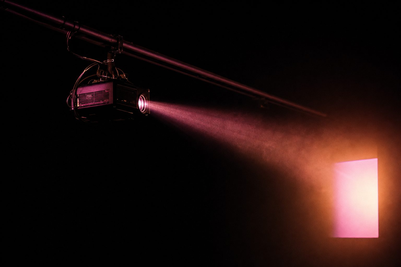
15.0m
THROW DISTANCE
- Throw ratio
- 1.5:1
- Image width
- 10.0 m
- Throw distance
- 15.0 m
- Image height 16:9
- 5.63 m
- Image height 16:10
- 6.25 m
- Diagonal 16:9
- 11.47 m
Geometry only. It does not account for lens shift, an off-axis position or brightness, all three can make a geometrically valid position unusable.
What throw ratio actually is
Throw ratio is one division: distance to the surface, divided by the width of the image it produces. A 1.5:1 lens at fifteen metres gives a ten-metre-wide picture. At thirty metres the same lens gives twenty.
It belongs to the lens rather than to the projector, which is the detail that catches people out. Swapping a body for a brighter one changes nothing about the geometry; swapping the lens changes every position on the plan.
Why it is quoted against width
Consumer projectors advertise a screen size as a diagonal, and that habit leaks into live work where it does real damage. The same diagonal describes a different width at 16:9 than at 16:10, so a distance derived from a diagonal is wrong by whatever the aspect difference is.
Every professional lens sheet quotes ratio against width. The calculator above returns heights and a diagonal as well, but the ratio itself is always width-based.
Zoom range as a working tolerance
Most live lenses are zooms, quoted as a range. At a rigging position you cannot move, that range is the span of image widths available to you, and it is usually more useful than the ratio itself: it tells you how much the design can change before the position has to.
A position that only works at one end of the zoom is a position with no tolerance, and load-in always needs some.
Throw ratio is a property of the lens, not of the projector. That single confusion accounts for most of the on-site failures of this calculation: a body is specified, a lens is assumed, and the image lands at the wrong width from the only position the room allows.
The order that works is the reverse of the order people use. Establish where a projector can physically stand, measure the width the image has to cover, and let those two numbers choose the lens, rather than choosing a lens and then negotiating with the building.
What geometry does not tell you
Three things sit outside this calculation and each can invalidate a perfectly good answer.
Brightness. Light per square metre falls with the area of the image, so doubling the width quarters it. A geometry that fits can still be far too dim, particularly against the haze and stage lighting discussed under light programming.
Off-axis position. Real rigging positions are rarely square to the surface. Correcting for that costs effective resolution, because part of the panel is being used to fill a shape it no longer matches, the mechanics are covered under projection mapping.
Obstruction. A projector at the correct distance is useless if the beam crosses a truss, a follow-spot position or the audience. That is a previs problem, and it is where these numbers should be tested before anybody orders a lens.
What the geometry does not tell you
The arithmetic gives distance, width and lens. It does not give brightness, and a geometrically correct position can still be the wrong one: a longer throw spreads the same lumens over more area, and haze in the throw takes a further share before anything reaches the surface.
Nor does it know about people. A position that works on paper and puts a projector where an audience walks, a camera needs to be, or a follow spot has to sit is not a position, and finding that out in the room costs a morning.
Where this fits
Projector positions are part of the physical budget set by stage architecture, and they are best resolved in the model during previs, where a wrong answer is free. What happens to the image once it lands is projection mapping, with the daily alignment handled by a dedicated mapping stage.
The equivalent arithmetic for an LED wall is the pixel-pitch calculator. Terms are defined in the glossary.
Questions
the things people ask about thisWhat is throw ratio?
Throw ratio is throw distance divided by image width. A lens marked 1.5:1 placed 15 m from the surface produces a 10 m wide image. It is a property of the lens, not of the projector body, so changing lens changes every distance on the drawing.
Does throw ratio use image width or the diagonal?
Width, always. Diagonal measurements appear on consumer projector boxes and cause a great deal of confusion on site, because the same diagonal gives a different width at 16:9 than at 16:10. Every professional spec sheet quotes ratio against width.
Why does the calculator ask for a lens range rather than one number?
Because zoom lenses are quoted as a range, 1.2–1.8:1, for instance. At a fixed distance that range is the span of image widths you can achieve without moving the machine, which is usually the number you actually need when the rigging position is not negotiable.
Does this account for lens shift or an off-axis position?
No, and that is deliberate. Throw geometry gives you distance and size; lens shift and keystone correction affect where that image lands and how much of it survives the correction. A steeply off-axis position costs effective resolution, which no ratio calculation shows.
What about brightness at that distance?
Brightness is a separate calculation and it is the one that decides whether the picture reads. Illuminance falls with the area of the image, so doubling image width quarters the light per square metre. A geometry that works can still be far too dim, and the two have to be checked together.